THE
ART AND SCIENCE OF SIMULCASTING REDUX
By
DENNIS CAMERON, TELCOM TECHNOLOGIES ASSOCIATES
It
has been almost 25 years since I
published my first simulcast
paper. While it was state-of-the-art
at the time, a lot of technology
has come along to make
it easier to implement
and improve the quality
of simulcast systems.
This paper will revisit
the history and theory,
and discuss the new technologies. [2/2/07]
[Reformatted
5/19/10]
History
While
PCS has intruded on some of the basic functions of paging
there are still a lot of paging/voice paging/messaging
systems around. The need for simulcasting has remained
constant, to provide paging/messaging over a wide area
and/or increase signal level within a given area. Also,
some hardy souls may be around whom are still simulcasting
voice.
Wide
area paging, at least in the US, started with “Ma
Bell”. These were bulky receivers that used two-tone
(then three-tone) signaling and simply beeped (thus
the term “beeper”) when signaled. Bell used
Hi-band VHF and started with a single transmitter. In
some cases they sequenced a second transmitter, and
in a few cases they “simulcast” non-overlapping
transmitters in conjunction with a sequence with other
non-overlapping transmitters.
 |
 |
Bell
had a different philosophy about paging, they were
the Phone Company, and saw paging as just another
way of generating phone calls. They applied a version
of the Erlang charts and determined the max number
of pagers they could handle on a channel was 500!
If they needed more capacity, they would apply
for a new channel. Because they were most interested
in generating phone calls, they had little desire
to use anything but tone only paging. Because they
were “Ma Bell” they did not worry too
much about capacity, if they ran out of capacity
on a channel (according to the Erlang charts) and
ran out of channels they would simply create a
waiting list.
At
the same time the FCC allocated paging frequencies for
the phone companies (wireline carriers), they also allocated
another group of frequencies for non-wireline carriers.
Because regulators viewed this allocation as common
carriage, its use also came under state control and
a certificate of convenience and necessity.
Most
of the early non-wireline carriers were answering services.
These operators were looking for additional income and
saw paging as a direct revenue generator. For the most
part these folks loaded channels to the max, and they
would basically continue loading until disconnects equaled
connects! They constantly looked for ways to increase
channel capacity. Back in those days only 6 channels
(4 lo-band and 2 hi-band VHF) existed, and in the larger
markets it was difficult to come by a channel, especially
with the protected areas associated with lo-band.
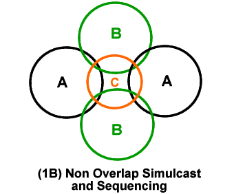
The
need for wide area coverage further drove the need for
improved channel capacity. Even with the advent of high
speed two-tone and five-tone paging formats the carriers
were running out of capacity because the only effective
way to go wide areas was to sequence the transmitters
or use the combination of simulcasting non-overlapping
transmitters in sequence with other non-overlapping
transmitters (see figs. 1A, B). In addition to capacity,
these methods still left a big problem in most major
markets, building penetration.
The
carriers were unable to get a signal into large buildings,
especially with lo-band. The problem came in two forms;
small apertures and reflective glass. Aperture has to
do with the windows on older buildings. In RF terms,
(this part will interest engineers and “teckies”) “aperture” is
an opening that an RF signal can pass through. The optimum
minimum aperture is ½ λ (wavelength).
A 35 MHz signal’s wavelength is about 28 ft (8.8
meters) long, which requires an aperture of 14’ (or
4.4 meters). Not too many buildings have windows this
large, so signals from these frequencies had difficulty
in penetrating into the interiors of the buildings.
Buildings that do have large windows often (especially
in warmer climes) are all glass exteriors but the glass
has a metallic content reflective surface. While this
design is ok for reflecting the sun and heat, it also
reflects RF signals creating the same problem as small
apertures.
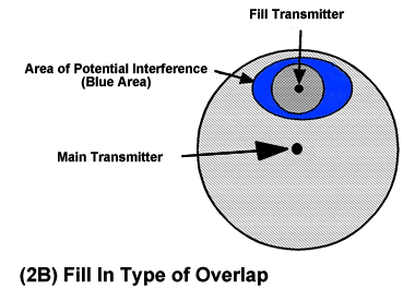
Carriers
tried to solve the penetration problem by installing “fill” transmitters.
In the larger markets this practice could require 3
or 4 fill transmitters further complicating the coverage
vs capacity issue. If they sequenced the transmissions,
then capacity was sacrificed. However, if they tried
simulcasting they would have large areas of interference
and their system would get clogged with re-calls. This
not only affected capacity but required more phone lines
to handle the calls (Ma Bell watched the lines and required
common carriers to have only so many busies on a line).
With
all these factors in play the carriers started asking
the vendors for solutions, and a few hardy carriers
started looking for their own solutions.
Early
attempts at simulcasting proved to be problematic at
best and completely useless at its worst. Most of these
early systems were attempted using wireline and, in
a few cases, microwave. Suffice it to say many man-years
were spent trying to make these systems work (to little
or no avail). When radio links were first tried it appeared
to solve the problem but as faster paging formats came
along (and voice paging was attempted) it was back to
the drawing board! It wasn't until about 1980 that the
first simulcast system that was designed from the ground
up as a fully coherent simulcast “system”,
was simulcasting truly successful.
The
basics
First,
the definition of simulcast (as used in the Land Mobile
industry): Simulcasting is the simultaneous transmission
of the same data (digital, analog or voice) through
two or more transmitters within the same geographical
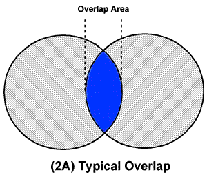
area. Another description for simulcast is controlled
multipath (we will look at that later). Diagrams 2A,
and 2B are examples of overlap areas. An overlap area
has been defined as an area where two or more RF signals
have signal strengths within 6 dB of each other. This
definition is only partially correct.
 |
 |
This
rule-of-thumb came about because of the differences
between AM and FM radios. Amplitude modulation,
as most of you know can be very noisy. The intelligence
(modulation) causes the amplitude of the signal
to vary. The noise (static, lightning, etc., rides
along with the amplitude peaks of the signal. Even
in strong signal conditions, noise can sometimes
be heard. With FM the intelligence (modulation)
causes the frequency or phase of the signal to
change. Noise still rides on the amplitude peaks
of the signal but a FM receiver has a circuit called
a limiter that cuts off the amplitude peaks. Because
the intelligence is on the frequency or phase differences
the limiter does not affect it but does greatly
reduce or eliminate the noise. Because the limiter
kicks in at about 6dB above the minimum signal
level needed to hear a signal this parameter is
known as the “capture ratio”, or, the
receiver’s ability to capture signal over
noise.
Designers
then thought that if the overlap signal had a difference
of 6 dB, no simulcast effect would exist. The problem
with this conclusion is that the interference caused
by overlap signals consists of both amplitude and phase
noises. While the limiter could deal with some of
the amplitude interference, it can do nothing with the
phase noises. Unfortunately, half or more of the overlap
interference components are phase noises. In addition,
a large portion of the amplitude noise is caused by
the RF signals beating together.
(WARNING:
Teckie session ahead). The reason some of the amplitude
noise is a problem has to do with the RF beat note.
In almost all simulcast systems (past and present) each
transmitter must generate the carrier signal using an
oscillator. Because it is difficult to synchronize,
oscillators. Even today, they are essentially free running
(in relation to each other) devices. In any overlap
area the signals generated by these oscillators will
go in and out of phase with each other. While in phase
(assuming near equal signal strength), the RF signals
will add together giving a stronger signal. As these
signals start to go out of phase they eventually reach
180° out of phase. This is known as a Zero Crossing.
As the phase difference approaches 180°, the signals
will start subtracting from each other until there is
no signal left (still assuming near equal signal strength).
At this point there will be nothing but noise. Rising
and then lowering of the noise will occur on either
side of the zero crossing point. So, from approximately
110° to 250° there will be a noise pulse that
contains both amplitude and phase noise. If you are
listening to this signal on a regular FM receiver it
will take on the properties of a beat note.
The
frequency of the beat note will be determined by the
relative offset and the stability of the oscillators.
The strength or amplitude of the beat note is determined
by the relative signal strength of the two signals in
the overlap areas.
Getting
overlap areas under control was nearly impossible
until the advent of ultra-high-stability oscillators.
Although these devices are very expensive , they
were far cheaper than any other method of achieving
high stability. Even today, they are still the
best way of achieving stability.
The
second part of simulcasting is the distribution
of the data to and through the transmitters. Long
after the advent of “hi-stab” oscillators
carriers still could not get simulcast to work
properly. Two reasons accounted for this problem:
(1) distribution of the base band signal to the
transmitter and (2) the transmitter itself.
In
the beginning, almost all carriers used phone lines
for distributing signal to the transmitters. While
this approach was a good method of distributing
to a single transmitter, it became a disaster when
used with simulcast. Without going into mind numbing
detail, the problems with phone lines are many.
First, line length is a major problem. On a phone
line, length equates to time; therefore, the more
length, the more time (See Fig 3).

Because
Phone Companies cannot guarantee particular path
it was always an unknown as to how long the line
would be. As the length grew, so did the delay.
If one line is twice as long as the other the signal
will be delayed by a time that is equal to the
length of the line. Being twice as long the signals
will be 180° out of phase and assuming about
equal signal level, they will cancel each other.
Various lengths would produce various phase differences
in the overlap areas, which in turn caused varying
levels of distortion. Although this can be corrected,
there are other factors such as frequency response,
envelope delay and just the nature of the copper
wires themselves. To make a long story short, phone
lines never worked out well for high speed paging
formats or voice paging.
Some
of the carriers tried light-route microwave but this
solution also has its own set of problems. First, it
can be very expensive if the transmitter sites do not
match the microwave drops, second, most of the multiplex
(MUX) in use for "light route" microwave (almost
the only type available to use for simulcast distribution)
uses a multiplex method known as single-sideband,
suppressed carrier (SSBSC). With SSBSC multiplex,
absolute phase can be controlled from one end of a channel
to the other. However, there usually is no way to control
the phase from one channel to the next just as there
is no way to control phase from one line to the next
with the Phone Company
Finally,
some hardy souls tried radio links and things seemed
to get better. With radio links there is usually just
one distribution transmitter per geographic system.
Because most links were phase modulated each receiver
was locked to the transmitter which reduced phase jitter.
It was a great solution for two-tone paging. However,
when five-tone, POCSAG, GOLAY and voice paging was tried
the problems started all over again.
The
problems had to do with the radio links and the audio
circuits of the paging transmitters. For various technical
and regulatory reasons these radios had circuits in
them known as pre-emphasis and de-emphasis. Again, without
going into detail, these circuits had wide, loose frequency
and phase responses and could not give good, consistent
performance for the higher speed paging and voice paging
systems.
In
the early ‘80s Quintron (a paging transmitter manufacturer)
took a long look at the problems facing simulcast and decided
to correct the problems. First we (yes, I
worked there) approached simulcast as a system instead of individual
pieces of equipment. We then took each piece of the system and
matched the electrical characteristics to each other, removing
or redesigning any circuits that could cause a problem. We did
this for wireline systems and radio links. We then worked out
procedures to optimize a system for any type of area (urban, suburban,
open country, etc.). The rest is history. Wide area paging systems
started popping up all over the country (and a good part of the
world). There were even two-way voice systems (some very large).
There was such a demand for paging (and messaging) higher speeds
were required to handle the capacity.
Today,
most of the early type systems have
been replaced with newer technologies.
While high-stability oscillators
are still in use in the transmitters,
the rest of the modern simulcast
system is new. The analog paging
transmitters have been replaced
with precision digital transmitters.
GPS has allowed systems to use store-and-forward
methods that have superior phase
and delay characteristics that are
far better than any analog system.
Store-and-forward
uses GPS to provide a precise timing
pulse to synchronize various circuits
starting with the NOC system controller
and the individual transmitter simulcast
controllers. The timing pulses are
corrected for geographic position
by the GPS system. Data generated
in the NOC forms the paging codes
and message data and assigns a time
slot (a given number of clock pulses
after the transmitter controllers
receive the data) to transmit that
particular information. Each transmitter
transmits the page/message based
on what the NOC timing has indicated,
plus or minus any time offsets programmed
into each controller. This method
removes any time and phase differences
introduced by the distribution medium.
With
the advent of store-and-forward
it is again possible to use phone
lines or microwave or satellite
systems, as well as radio links,
to distribute the signal to transmitters.
Systems can now cover large areas
(nationwide, regional) with little
or no problems (but setup and maintenance
procedures are still required).
Although some smaller systems and
voice systems still use analog transmitters
and link distribution, most have
switched to pure digital.
With
the advent of modern cellular and
its attendant messaging features
paging has lost some of its luster.
However, hundreds of small systems,
as well as some larger systems,
continue to provide service to thousands
of customers who demand the best
possible coverage and assured message
delivery.
What
started as a simple adjunct service
has, for almost 50 years, continued
to deliver what the customers want
and need. I don’t think paging
will ever go away!
Anyone
wishing a more in-depth engineering
paper on this subject can request
it by e-mailing me at dcameron@ttagroup.com I
will email you the paper.
Dennis
Cameron, along with Bill
Hays, own Telcom Technologies
Associates, a consulting
firm specializing in RF
communications. He has
extensive experience in
high-speed paging, satellite
communications, two-way
communications, IP distribution,
microwave and communications
control systems. Most
of the last 35 years has
been spent in engineering
management with most of
the time being "hands-on" management.
In addition, Cameron has
had multiple patents issued
in the field of radio
communications and has
done advanced communications
research with the University
of Mississippi. Cameron
was one of the prime developers
of modern simulcasting
and has published several
papers and articles on
the subject. He has designed
and implemented many one-way
and two-way simulcast
systems.
|